If you are lucky enough to live in a city with old buildings and a crowded rental market, then you have probably encountered a window air conditioner. In most residential rental properties of NYC, they are the de-facto standard . Central air conditioning is only found in new construction, but sometimes not even then. I have the great privilege of owning two units. The Friedrich CP08G10 for my 200 square foot bedroom, and the GE AEM12ARW1 for the remainder of the apartment. They have been the source of much frustration.
Read on for an adventure in my quest for both comfort and expense control.
The Problem
Skip this if you just want to read the nerdy details, and not a rant about window units
Both units do a decent enough job, but a fundamental design flaw prevents any window unit from doing a great job. The intake is located next to the output. During a hot summer day, this means you need the A/C fan, and any ceiling fans, on full blast to get any kind of circulation. Otherwise, it ends up cooling the air it just spit out. This is horribly inefficient, and makes for a hot apartment while it takes its sweet time cooling it down. A future project of mine may be solving this with some custom duct work (see duct tape and dryer vents), but the challenge there would be aesthetics.
Since these units are wonders of efficiency, I would prefer to not having them running all day while I’m at work. I also prefer not to come home to a deathly hot apartment. The manufacturer’s way of solving this is by offering a timer function. I can set the unit to turn on (or off) after 1-24 hours in 1 hour increments. This is great if I know precisely when I will be arriving home as I leave for work in the morning. More often than not, I don’t know this.
Solution #1: Buy a fancy A/C
Friedrich has a new line of units called Kühl that offer remote control via mobile app. While I’m sure it is nice, I’m not spending the money to replace my units for just this. It also doesn’t solve the temperature sensor issue.
Solution #2: coolNYC
My initial solution to all of this was to sign up for the free coolNYC program through Con Edison. They provide equipment from ThinkEco: a modlet and a remote control for each unit, a control box hooked up to your internet connection, and some software. The modlet is essentially a remote control relay and current sensor. The remote control is just on/off plus temperature control. This was a big improvement from before, and is great for anyone who doesn’t like to tinker with things. I had three problems with the program:
- The remote also acts as the temperature sensor. While this is better than in the unit itself, it couples the measurement point with the control point.
- The modlet only offers on/off control. You turn on the unit, and set it to your desired settings (usually the coldest temperature in the A/C mode). The relay then turns the unit on/off. Again we are offered limited control, and we must know the settings ahead of time.
- The software allowed you to set time schedules (again not convenient), control manual on/off, and see usage. The on/off was more cumbersome than it needed to be (I just need a damn button), and didn’t always work because of “connection issues”.
Solution #3: Spark Core
After enough frustration with the coolNYC equipment, I decided to build my own. I happened to have a Spark Core that I received at JSConf US lying around. A cloud connected microcontroller with Wi-Fi was exactly what I needed. Both of my A/C units came with infrared remote controls for all the functions. I’m going to use this to my advantage. I’m going to start with my bedroom unit, the Friedrich.
Infrared capture
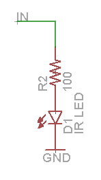
The first step was to build a circuit to capture the infrared signals from the remote. The circuit is pretty simple as diagrammed below. The resistor pulls down the output until the IR detector switches on to pull it high. I used this infrared detector from sparkfun.
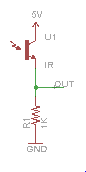
I have a working circuit, but I need something attached to OUT to actually capture the signal. I used a USBee SX logic analyzer. Here is what the power on signal looks like.
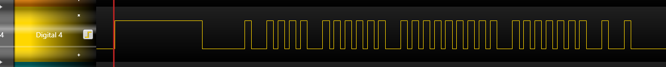
The red line is the trigger, which determines when the logic analyzer starts saving data. I set it to trigger on the first rising edge, and to have the trigger at the start of the data.
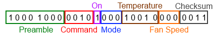
In order to start making sense of what the signal actually is, and how to decode it, I start reading. Darell Tan has a great set of posts where he talks about a similar procedure, but using an Arduino for capturing instead of a logic analyzer. From that I can see that my remote is using pulse distance encoding because the duration of the highs is always the same. Decoding this signal then, starting after the header, is 1000100000100000000100000011 or 0x8820103. After a couple more captures of different operations, the size becomes clear. The signal is always 28 bits.
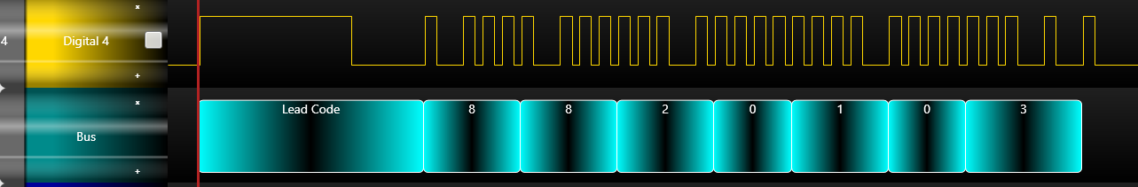
With encoding and bit size in hand, I decide to use a trick to speed things up. The USBee software has the ability for the user to write custom protocol decoders in the .NET framework. The sample code happened to come with an NEC IR decoder, which was close to what I needed. The only major change I had to make was outputting a nibble (4 bits) at a time instead of a byte since 28 is not evenly divisble by 8. I’ve posted my custom protocol decoder if anyone wants to take a look. Now let’s take another look at that power on signal.
IR remote protocol
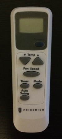
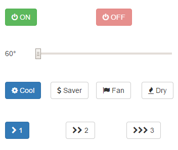
The remote control has 7 buttons as you can see above.
- Power On/Off
- Temperature Up (max 86)
- Temperature Down (min 60)
- Fan Speed (1, 2, 3)
- Timer
- Mode (Cool, Money Saver, Fan Only, Dry)
- Auto Swing - toggles the airflow oscillating left to right (really doesn’t do much)
I don’t care about the timer function, so I go about capturing all the different combinations I can think of. Capturing all the temperatures from 60 to 86 in Cool mode on fan speed 1 gives the following table.
A clear pattern emerges for the 5th and 7th nibble. The 5th nibble counts up from 1-16, wraps and back up to 11. This matches nicely with the temperature with an offset of 59. The extra bit comes from the 1st bit of the 6th nibble. So bits 16-20 (0 index) are the temperature.
Usually these protocols have some sort of error checking. The receiver needs to know if it received the data correctly. Sometimes that is an XOR of bytes or nibbles. Since the last nibble counts up as the temperature does, we can infer that it is a checksum. A little fiddling shows it is the sum of the nibbles with no overflow.
Now to toggle the mode.
Only the 4th nibble is changing. Bits 13-15 are the mode. Fan speed is next.
Bingo. Bits 21-23 are the fan speed. Finally power on/off and auto-swing.
Power Off and Auto Swing seem to be constant. Power On is the same as the temperature control except for bit 12. At this point, I concluded that bits 0-7 are constant at 0x88. That leaves the following picture.
Infrared transmission
With the knowledge of what I needed to send, I needed to build the how. There was the physical part which was solved by this circuit. The LED is again from sparkfun.
IN will be connected to the Spark Core. Any pin will do, as long as it supports Pulse Width Modulation (PWM). I chose D0. The reason we need PWM is because the signal is not simply digital 1s and 0s. It is modulated on a 38kHz carrier signal. We will use a PWM timer at that frequency and then just control the duty cycle, how much of the period the output is high, switching between 0 and ~33%.
Software
Here comes the fun part, hooking this all up to the Spark Cloud and controlling it. The transmit part of the code is fairly straightforward. Just changing duty cycle to 33% for a specified time period, then turning it off to send a digital high. The timings all came from measurements I made with the logic analyzer. Composed together as functions, it made it easy to write code that was just send(0x88c0051, 28);. All the code is on GitHub for your perusal.
The one snag was because the Wiring interface for Spark currently doesn’t allow changing the PWM frequency. The default is only 500Hz, so that clearly won’t do. I luckily found a thread in the forums with some code to change it to 38kHz (or whatever you want). Support for changing it from Wiring is coming.
The neat part comes in the form of Spark.function and Spark.variable. Spark.function allows you to expose a function as controllable from the Cloud Code API. This allows me to send a HTTP POST request and change the temperature, for example. Spark.variable allows you to expose a variable in the API for read access. This let me expose the current temperature setting, on/off status, mode, and fan speed as simple HTTP GET requests.
That is everything needed for the firmware. The final piece is a simple web page to fire off the API requests to read/write everything. I wrote a simple React.js interface to do this in tandem with SparkJS, the JavaScript API library. Again, all the code is on GitHub. I know the design is terrible, but I will improve it.
Conclusion
Spark Core made this super easy to do. I imagine I will be doing a lot more projects with it. There is also the Spark Photon which was just announced for $19 USD. Future tasks include building a more permanent enclosure, remote temperature sensors to automatically turn on/off, reverse engineering my other A/C unit, and improving the web interface.